ESP8266 setup
April 12, 2016
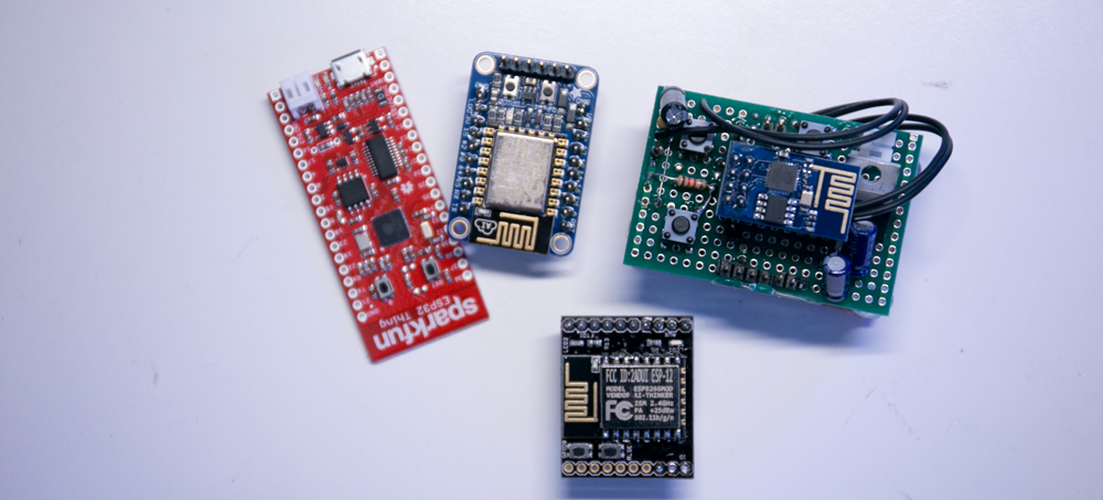
I finally got around to playing around with the ESP8266 breakout boards (ESP8266-01) I had sitting on the bench. The community support for these has improved a lot recently although there is still some signal to noise problems between old and new information when googling.
Hardware set up
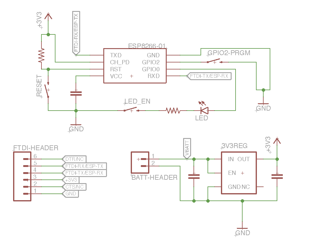
The AT firmware preloaded on the ESP module should work out of the box, but if you’re planning on reflashing it you’ll need to be able to trigger it’s reset pin while pulling GPIO2 pin low to trigger the bootloader.
Here’s a quick diagram of the setup I used for the ESP8266-01 breakouts I had.
I initially had some issue uploading firmware to the ESP. The AT commands were working fine and I was able to read the device’s mac address with esptool.py, but I was unable to upload new firmware programs. It turns out the Bus Pirate I was using as a serial bridge wasn’t reliable enough for the firmware transfers at speed. So I would suggest you use an FTDI cable or other well known and widely used serial/USB converter when you’re first setting up. Once I switch to the FTDI cable everything worked smoothly.
AT commands and Serial Setup
By default when you boot your devices (without holding GPIO2 low) you’ll get the AT firmware which lets you control the chip over UART as a peripheral WIFI device. There’s a couple different sets of documentation for the AT commands. Depending on your device and current firmware you may not have all the commands available to you, but the basics should always be the same. Here’s a copy of the latest espressif AT command documentation.
You’ll need to a serial terminal. If you’re on a mac like me the simplest option is screen, but you might also want to try something like CoolTerm for some handy advanced options like enter key emulation.
Apparently not all the AT firmware versions run the same baud rate. The modules I had defaulted to 9600 baud but you’ll just have to cycle through different speeds until you figure it out.
Note that the AT firmware requires you to terminate your lines with CR+LF, e.g. ASCII 0x0d 0x0a. If you’re using CoolTerm you can go configure this under Options->Terminal->Enter Key Emulation. If you’re using screen the enter key only send the CR character so you’ll have to enter Ctrl-meta Ctrl-J to send the LF character afterwards. Supposedly it’s also possibly to configure the enter key behaviour for screen by calling stty onlcr once screen is running but I haven’t tested this.
I fired up screen by running screen /dev/tty.usbserial-A700e76L 9600, obviously you’ll need to subsitute the correct tty/COM device and/or baud rate.
You can hello world your ESP like so:
AT
You should get a response like:
OK
We can try something a little fancier like sending a request. Here’s a couple lines that will connect to WIFI and make a request to pushover a programatic notification service.
First we connect to the network (JAP = Join Access Point)
AT+CWJAP="you-wifi-ssid","your-secrect-wifi-password"
Now start a TCP connection
AT+CIPSTART="TCP","api.pushover.net",80
And initiate sending some data. Note that 209 here is the number of characters in my subsequent request
AT+CIPSEND=209
Now we send our simple HTTP POST request over the TCP connection. The Content-Length is simply the number of characters in the message body:
token=mysecrettoken&user=myusertoken&message=test
So putting that all together we get:
POST /1/messages.json HTTP/1.1
Host: api.pushover.net
Content-Type: application/x-www-form-urlencoded
Content-Length: 49

token=mysecrettoken&user=myusertoken&message=test
And finally close the TCP connection
AT+CIPCLOSE
Bootloader Mode: Reading the MAC Address
If we want to go beyond the default AT firmware, the esptool.py which I was mentioning earlier is is available on GitHub. It seems to be the go-to tool for uploading binaries and talking to the ESP in bootloader mode from the command line.
If you reboot your ESP while pulling the GPIO2 pin low, you can then test the esptool.py by reading the mac address of your module (the bootloader seems to run at 115200 baud). Again you’ll need to subsitute the correct tty/COM device and/or baud rate in the examples here.
./esptool.py --port /dev/tty.usbserial-A700e6Gc --baud 115200 read_mac
You should get a response like this (but with a different mac address);
Connecting...
MAC: 18:fe:34:f4:eb:30
Confusion with Flash Sizing and Restoring the Stock AT-Firmware
As an exercise, I wanted to make sure I could reflash/restore the stock AT firmware. It turns out that it can be tricky to find the correct version of the most recent version of the espressif AT firmware. In general you can find the original firmware within the espressif SDK which is (currently) available on the espressif forum. The ES8266.com forum seems to also be working on some “improved variants” of the AT firmware.
Some links:
- Espressif forum, search here to get the latest official SDK
- Most recent SDK as of writing this
- ESP8266.com forum
If you’re working from the espressif SDK, which is what I’m doing, you’ll need to look in /bin/at in the SDK folder. In the latest version they have a fairly useful readme.txt file exlaining which files you need to use and where they should be uploaded into memory. This is the caveat of using the official SDK, you have to upload a number of different binary firmware blobs to different memory regions.
This led to my next confusion with the flash memory sizing. This matters because the more recent AT firmware have some options for OTA (over the air) updates that require larger flash memory sizes to function. This is basic stuff, but it’s easy to get confused with the conversion between Mbit and Mbyte and it can be a little obtuse to figure out which flash chip is on your ESP board.
First let’s figure out what flash chip we have by running:
./esptool.py flash_id
You should get a crytpic response like this:
Connecting...

Manufacturer: c8
Device: 4013
Then confusingly you can refer to this header file to figure out what actual part number that Manufacturer and Device number refers to. In this case we have Manufacturer (0x)c8 and Device (0x)4013 which is associated with the GD25QB flash chip. We’re actually missing some information so I had to look at physical part on the board to establish that it’s the GD25Q40B chip. Now we can look up this part number and determine the size of the flash chip which will be important for choosing the AT firmware (and also for configuring you toolchain or Arduino IDE later). Keep in mind distinction between Mb(it) and MB(yte), 1 MB(yte) is 8 M(bit). Different forums and documentation may use one of the other. In my case the GS25Q40B is 4 Mb(it) or 512 KB(yte).
I also have some more recent ESP12e boards. These have Manufacturer (0x)e0 and Device (0x)4016 which is associated with the W25Q32BV chip. It has 32 Mb(it) or 4 MB(yte) of SPI flash memory.
Once you’ve got that sorted out you can look at the readme.txt in the ESP SDK and try flashing your AT firmware. You will need to adjust the exact esptool.py command based on which firmware version and chip size you’re using.
Here’s an example where I flash a 4 Mb(it) or 512 KB(yte) chip. This means we’ll the default AT firmware without OTA updates (the only option for such a small flash chip).
./esptool/esptool.py --port /dev/tty.usbserial-A700e6Gc --baud 115200 write_flash 0x00000 boot_v1.2+.bin 0x01000 at/512+512/user1.1024.new.2.bin 0xfc000 esp_init_data_default.bin 0x7e000 blank.bin 0xfe000 blank.bin
Notice how this matches up with the readme.txt section for an 512 KB(yte) flash size:
download:
Flash size 8Mbit: 512KB+512KB
boot_v1.2+.bin          0x00000
user1.1024.new.2.bin    0x01000
esp_init_data_default.bin       0xfc000 (optional)
blank.bin               0x7e000 & 0xfe000
Note that the files referenced by the readme.txt are spread around various folders (/bin /bin/at/*, etc) in the espressif SDK so you might need to poke around to located them.
Arduino IDE
In order to quickly start my project I decide to try the ESP8266 Arduino plugin which works surprisingly well. Installing it is pretty straight forward via the Arduino board manager and well documented on the GitHub page. You’ll probably want to glance over it’s documentation, specifically the libraries since some of them don’t work exactly like their Arduino counterparts due to the differences in hardware.
There are quite a large number of options when configuring the upload for the ESP8266 in the Arduino IDE, but I had success with the default setttings. You may eventually want to configure the “Flash Size” option to match your device.
Streaming Sensor Data over UDP/OSC to SuperCollider
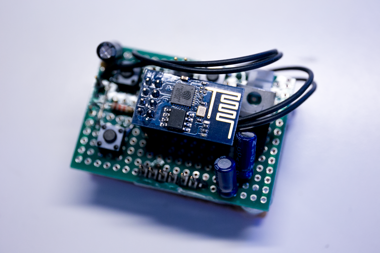
The project I had in mind was to hook up the ESP to an IMU and stream the data to SuperCollider, a sound synthesis programming language.
I wired the ESP up to an MPU-6050 IMU breakout from sparkfun. You can see the wiring and the protoboard below. I also hooked up a linear 3.3V regulator with a LiPo battery. I used an LM1117, which is really not an ideal choice since it struggles to provides 3.3V from the LiPo. Even fully charged I was only getting 3.1V - 3.2V from the regulator. But it was the only regulator I had on hand so I made due.
Here’s the source for my ESP/Arduino firmware which uses the Arduino OSC library from CNMAT. You can see me setting up the WIFI and UDP data. Currently I’m just hardcoding the (statically allocated) IP address and port of the target computer, something more intelligent with multicasting would probably make the project more flexible.
A cautionary note about the CNMAT OSC library, it uses dynamic memory allocation (e.g. it calls malloc) which may not be desirable for an embedded application like this where limited memory can make memory fragmentation and memory leaks a big problem. I’ve subsequently been using tinyosc instead which leaves the memory allocation to you.
#include <ESP8266WiFi.h>
#include <WiFiUdp.h>
#include <Wire.h>
#include <OSCMessage.h>

#define MPU9150_ACCEL_XOUT_H       0x3B
#define MPU9150_ACCEL_XOUT_L       0x3C
#define MPU9150_ACCEL_YOUT_H       0x3D
#define MPU9150_ACCEL_YOUT_L       0x3E
#define MPU9150_ACCEL_ZOUT_H       0x3F
#define MPU9150_ACCEL_ZOUT_L       0x40

#define MPU9150_GYRO_XOUT_H        0x43
#define MPU9150_GYRO_XOUT_L        0x44
#define MPU9150_GYRO_YOUT_H        0x45
#define MPU9150_GYRO_YOUT_L        0x46
#define MPU9150_GYRO_ZOUT_H        0x47
#define MPU9150_GYRO_ZOUT_L        0x48

int MPU9150_readSensor(int addrL, int addrH);
int MPU9150_readSensor(int addr);
int MPU9150_writeSensor(int addr, int data);

const char* ssid = "my-wifi-ssid";
const char* password = "my-wifi-password";

// I2C address 0x69 could be 0x68 depends on your wiring.
int MPU9150_I2C_ADDRESS = 0x68;

WiFiUDP udp;

byte gyroVal[6];
byte accelVal[6];

void setup() {
	Serial.begin(115200);
	delay(10);
	// Connect to WiFi network
	Serial.println();
	Serial.println();
	Serial.print("Connecting to ");
	Serial.println(ssid);

	WiFi.mode(WIFI_STA);
	WiFi.begin(ssid, password);

	while (WiFi.status() != WL_CONNECTED) {
		delay(500);
		Serial.print(".");
	}
	Serial.println("");
	Serial.println("WiFi connected");

	// Print the IP address
	Serial.print("ESP IP address: ");
	Serial.println(WiFi.localIP());

	udp.begin(8000);

	Wire.begin(0, 2); // Wire.begin(sda, scl)

	// Clear the 'sleep' bit to start the sensor.
	MPU9150_writeSensor(MPU9150_PWR_MGMT_1, 0);

	MPU9150_writeSensor(MPU9150_GYRO_CONFIG,  (2 << 3)); //change range of gyro to 3rd mode
	MPU9150_writeSensor(MPU9150_ACCEL_CONFIG, (2 << 3)); //change range of gyro to 3rd mode
}


void loop() {
	udp.beginPacket("192.168.1.100", 57120); // 57120 is the port supercollider uses

	OSCMessage msg("/data");

	msg.add(MPU9150_readSensor(MPU9150_ACCEL_XOUT_L, MPU9150_ACCEL_XOUT_H));
	msg.add(MPU9150_readSensor(MPU9150_ACCEL_YOUT_L, MPU9150_ACCEL_YOUT_H));
	msg.add(MPU9150_readSensor(MPU9150_ACCEL_ZOUT_L, MPU9150_ACCEL_ZOUT_H));

	msg.add(MPU9150_readSensor(MPU9150_GYRO_XOUT_L, MPU9150_GYRO_XOUT_H));
	msg.add(MPU9150_readSensor(MPU9150_GYRO_YOUT_L, MPU9150_GYRO_YOUT_H));
	msg.add(MPU9150_readSensor(MPU9150_GYRO_ZOUT_L, MPU9150_GYRO_ZOUT_H));

	msg.send(udp);

	udp.endPacket();
}

int MPU9150_readSensor(int addrL, int addrH){
	Wire.beginTransmission(MPU9150_I2C_ADDRESS);
	Wire.write(addrL);
	Wire.endTransmission(false);

	Wire.requestFrom(MPU9150_I2C_ADDRESS, 1, true);
	byte L = Wire.read();

	Wire.beginTransmission(MPU9150_I2C_ADDRESS);
	Wire.write(addrH);
	Wire.endTransmission(false);

	Wire.requestFrom(MPU9150_I2C_ADDRESS, 1, true);
	byte H = Wire.read();

	return (H<<8)+L;
}

int MPU9150_readSensor(int addr){
	Wire.beginTransmission(MPU9150_I2C_ADDRESS);
	Wire.write(addr);
	Wire.endTransmission(false);

	Wire.requestFrom(MPU9150_I2C_ADDRESS, 1, true);
	return Wire.read();
}

int MPU9150_writeSensor(int addr,int data){
	Wire.beginTransmission(MPU9150_I2C_ADDRESS);
	Wire.write(addr);
	Wire.write(data);
	Wire.endTransmission(true);

	return 1;
}
In addition here’s a short python script to debug the incomming OSC data. This script uses pyOSC.
import OSC

server = OSC.OSCServer(("", 52710))

def msg(path, tag, args, source):
	print path, args

server.addMsgHandler("/data", msg)

while True:
	server.handle_request()
For those familiar with super collider here’s a quick GUI interface that will plot the incomming sensor data
(
var prevAccel = [0, 0, 0], prevGyro = [0, 0, 0];
var accel = [0, 0, 0], gyro = [0, 0, 0];
var accelRange = 8000, gyroRange = 20000;
var index = 0, window, userView, osc, staticTexts;

window = Window("", Rect(0, 0, 1000, 700));
window.front();

userView = UserView(window, Rect(0, 0, 1000, 700));
userView.background = Color.white();
userView.drawFunc = {
	var height = userView.bounds.height, width = userView.bounds.width, power = 0;
	if (index > width,
		{ index = 0; userView.clearDrawing(); }
	);

	3.do({
		arg i;
		Pen.strokeColor = Color.hsv(i.linlin(0, 6, 0, 0.999), 1, 0.75);
		Pen.line(
			Point(index - 1, prevAccel[i].linlin(-1 * accelRange, accelRange, 0, height/6) + (height / 6 * i)),
			Point(index, accel[i].linlin(-1 * accelRange, accelRange, 0, height/6) + (height / 6 * i))
		);
		Pen.stroke();
	});

	3.do({
		arg i;

		Pen.strokeColor = Color.hsv((i+3).linlin(0, 6, 0, 0.999), 1, 0.75);
		Pen.line(
			Point(index - 1, prevGyro[i].linlin(-1 * gyroRange, gyroRange, 0, height/6) + (height / 6 * (i+3))),
			Point(index, gyro[i].linlin(-1 * gyroRange, gyroRange, 0, height/6) + (height / 6 * (i+3)))
		);
		Pen.stroke();
	});

	(accel ++ gyro).do({ arg item, i; staticTexts[i].string = "%".format(item.round(0.1)); });

	prevAccel = accel;
	prevGyro = gyro;
	index = index + 1;
	{userView.refresh}.defer(1/60);
};
userView.clearOnRefresh = false;

["Accel X", "Accel Y", "Accel Z", "Gyro X", "Gyro Y", "Gyro Z"].do({
	arg item, i;
	var text;
	text = StaticText(window, Rect(10, window.bounds.height / 6 * i, 200, 20));
	text.string = item;
});
staticTexts = Array.fill(6, { arg i; StaticText(window, Rect(10, window.bounds.height / 6 * i + 20, 200, 20)) });
staticTexts.do({ arg item; item.string = "0" });

osc = OSCFunc({
	arg msg, time, addr, recvPort;
	accel = msg[1..3];
	gyro = msg[4..6];
}, '/data');

window.onClose = {
	osc.free();
};

)
Disabling the AP for better performance
When you program your ESP you can configure the WiFi mode. For the ESP this mean you’re choosing between station mode (WIFI_STA), access point mode (WIFI_AP) or a hybrid of both (WIFI_AP_STA). In station mode the ESP connects to an existing WiFi networks as a client, much like any other wireless device. In access point mode, the ESP creates a network others can join, essentially acting as router to which other devices can connect. Finally in hybrid mode, the ESP does both simultaneously; it can join an existing network while also hosting second network of it’s own.
With the Arduino IDE the WiFi.mode(m) command is used to set this mode. However by default Arduino configures the ESP in the hybrid WIFI_AP_STA. This will cause a noticable lag on boot while the ESP sets up the access point. You may also see other intermittent performance issues as it tends to this access point.
So if you’re planning to the ESP in station mode, I strongly encourage you to change the WiFi to station mode by calling WiFi.mode(WIFI_STA) in your setup.
Better ESP platforms
The big letdown with ESP8266-01 is that it only has two pins available for GPIO use. In addition you may not get much flash memory if you bought a cheap one. Luckily there are some really interesting breakouts for the ESP now. The sparkfun breakout, for instance, conveniently includes both a LiPo charger and an auto reset mechanism so you don’t have to hold the reset button when programming it. There is also a new more powerful iteration of the platform, the ESP32 with BLE, more pins and other goodies. It’s also available as a breakout from sparkfun among others.
Documentation and Other resources
- Official documentation from espressif on their forum
- Most current official documentation as of this writing
- Sparkfun has good tutorial for their ESP thing
- There is of course a full build tool chain for the ESP which can be more easily installed using esp-open-sdk
- There is an interactive LUA firmware for the ESP called NodeMCU
- There is an interactive Micropython framework for the ESP. Some install instruction are available on learn.adafruit.com